B2 MAINTENANCE & FRAULT TRACING.
ROUTINE INSPECTION AND MAINTENANCE.
It is important to carry out regularly inspection of the equipment. Small faults should be recified before they become serious.
a. Check aerial and earth wires and connections.
b. Keep plugs and sockets clean, slightly greased with vaseline, if outdoors.
c. Check control knobs, tighten grub screws if necessary.
d. Check spares kit and know how to pack it properly and quickly.
e. See that all valves and firmly in their sockets.
f. Keep inside of set clean with aid of a small brush.
g. Keep accumulators charged, terminals clean and slightly greased. Top up with distilled water to keep acid level above
the plates.
SIMPLE FAULT FINDING.
Faults divide into classes:
1. Breakdown or short circuit of some part resulting in stoppage of the unit (receiver, transmitter or power pack) accompanied by noise of sparking or smoke from the defective part). In most cases the fuses inn the power pack will blow immediately.
Action: Switch off quickly, disconnect power supply and inspect for fault. This will usually be found quickly.
Typical example, condenser broken down.
2. Disconnection or open circuit, of some part or wire resulting in the stoppage of this unit in which it occurs. This usually causes no risk of damage to equipment, which may be left in switched on whilst simple tests are carried out.
Typical faults: plug not making contact, wire broken, or resistor or coil open circuit.
3. Intermittent faults, which cause erratic behaviour of unit in which they are located. Usually due to poor connections in plugs, fractured wires or weak switch contacts and frequently defective valves.
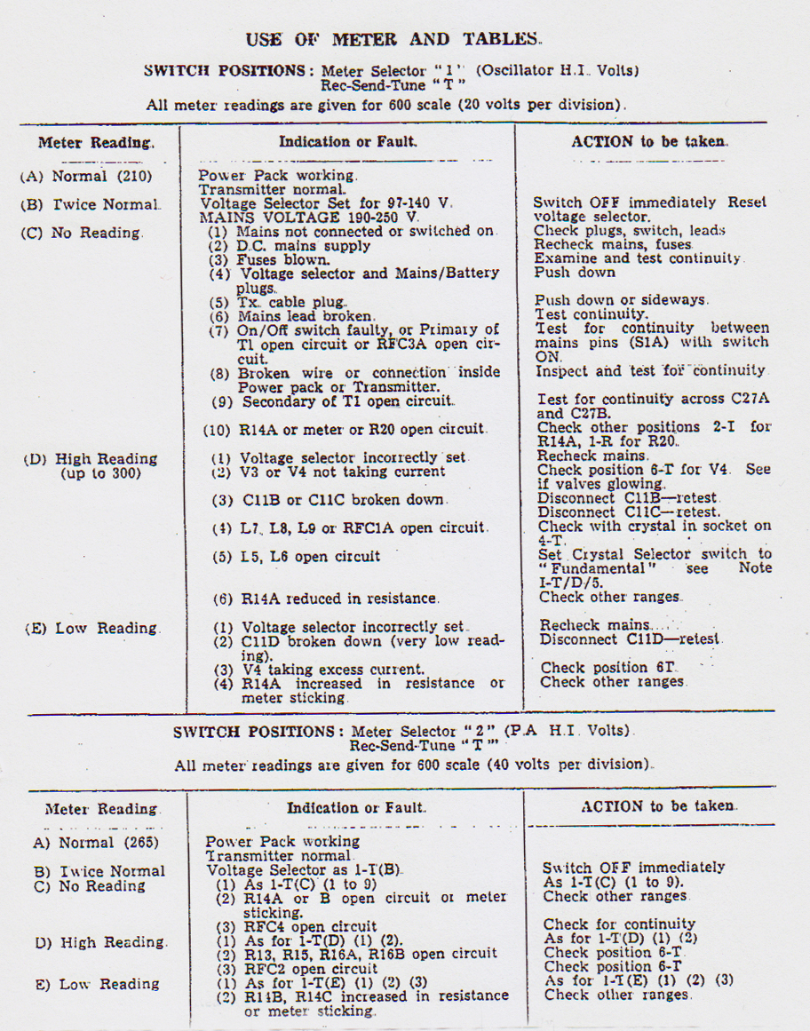
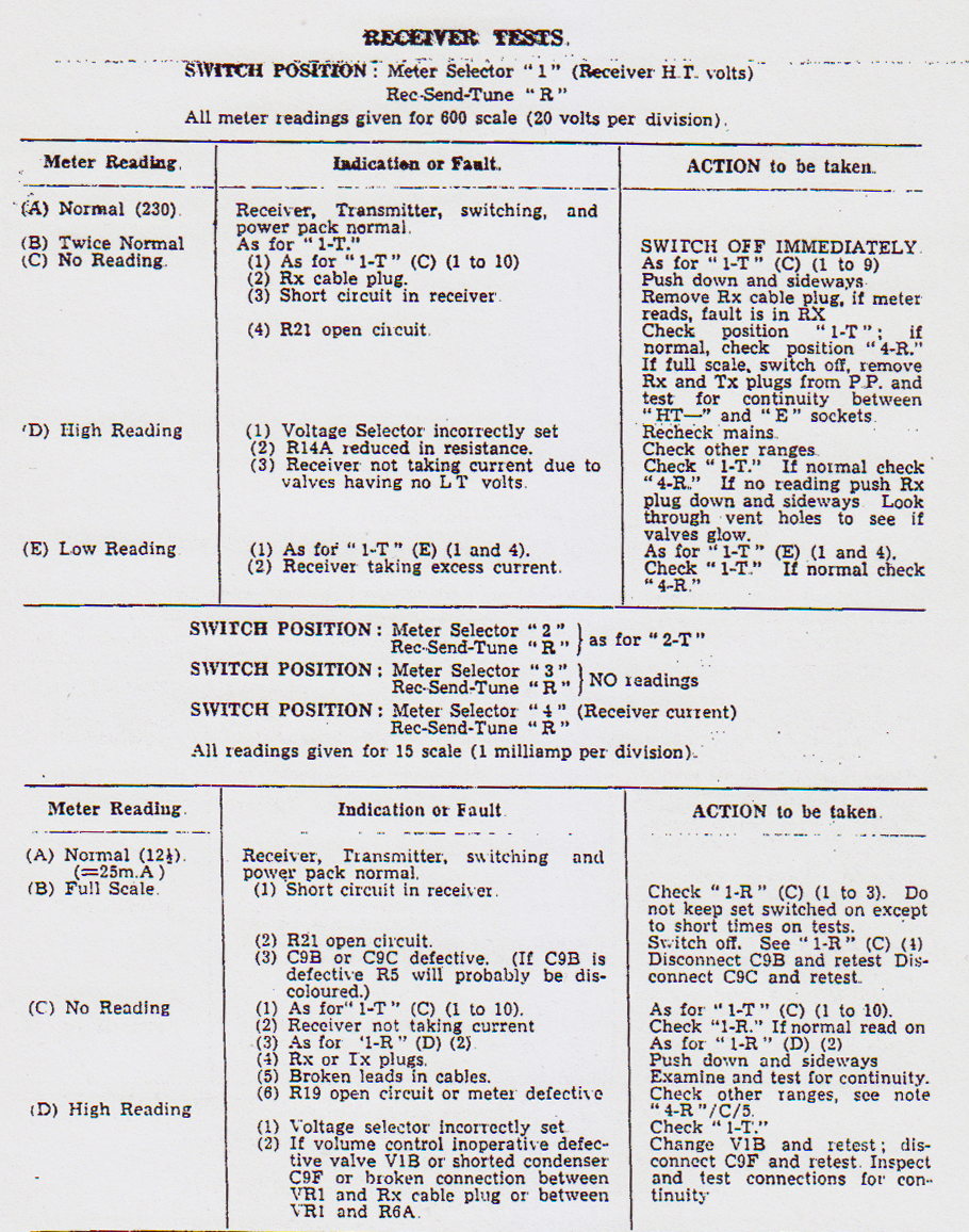
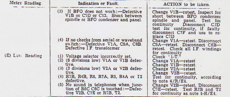
4. Deceptive Faults, frequently cause the fault finder to investigate some part of the circuit which is apparently defective when in fact the trouble may lie elsewhere. For example, a soft valve VIV causes the volume control to became inoperative, implying that it is faulty. Again, a bad contact or broken wire in the Power Pack may stop the receiver operating whilst not affecting the transmitter, thus implying that the Power Pack is in order and the receiver faulty, when the reverse is the case. To aid in finding such faults the following tables should be consulted. (The moral is to 'Look before you leap'). Some of the fault finding operations, especially those requiring immediate action on the part of the operator, should be committed to memory. In carrying out tests it must be remembered that although the voltages in the receiver are not high enough to cause more than an unpleasant shock, the voltages in the transmitter and Power Pack in certain places can be dangerous to life. NEVER BE CARELEES, DEATH IS PERMANENT. Do not carry out test inside units with power switched on, or the set might be damaged irreparably, which has the same effect as a dead operator., the message cannot be sent. The meter on the panel of the transmitter is provided with a switch ("Meter Selector") which enables the operator to measure the current or voltage in different circuits. The normal readings quoted in the tables are average for a number of wireless sets but will vary slightly from one set to another. if even a small part of the circuit is faulty, the meter will probably read more or less normal and if the amount by which each part affects the meter is known, then the fault may be found very easily.
Rule of Thumb Tests. Use Ears and Eyes.
Noise: The Power Pack normally has a faint low pitched mechanical hum when working on mains. The operator should accustom himself to this so that he may at once hear if something unusual is taking place. On vibrator operation from batteries the hum of the vibrator is distinctive and louder and again provides assurance of working or danger signal according to note. The receiver provides plenty of evidence of life, The normal hiss of the receiver in the telephones at maximum volume indicates that all is well. Reducing the gain control should reduce the noise. Switching on the BFO should produce a click and an increase of hiss if the BFO is working properly. Switching from one wave band to another causes clicks in the telephones. Touching the metal aerial socket with any metal object should produce clicks if the Frequency changer unit is working. The transmitter produces no characteristic noise and use must be made of the mter provided. Observation that all plugs are pushed well into their sockets should be instinctive to the operator. The glow of valves may be observed through ventilating holes in the cases of the units.
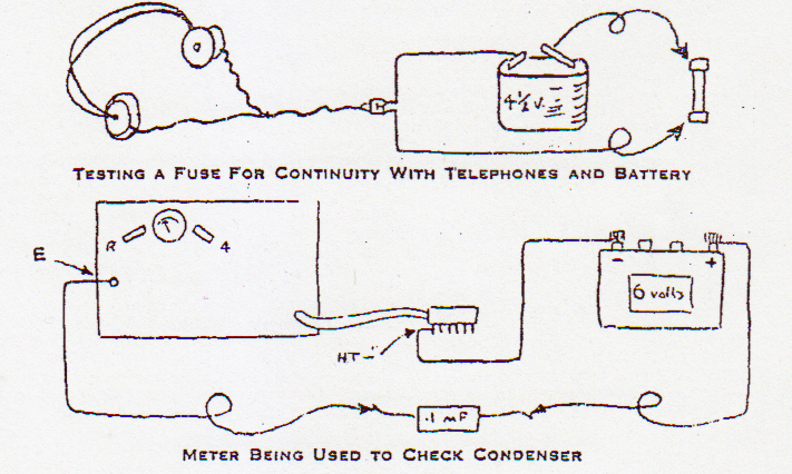
Continuity Tests. Use of Headphones and Meter.
The simplest method of determining whether, or not, a connection between two points or a coil or a resistor is broken, is to use the telephones and any dry battery or accumulator of 1½, 2, 3, 4, 4½ or 6 Volts. When a pair of telephones is connected across a battery a click will be heard when contact is made. Now if the connection is made to the battery through a lead which is suspected of being broken, if a click is heard the lead is in order, or if no click is heard the lead must be broken in some place. This method is useful and may be employed to test coils, transformers, resistors, leads from sets to cable plugs, mains, lead, etc. It is not a satisfactory method of testing condensers however, since the charging up current of a good condenser will cause a click and give the impression that it is broken down.
The meter in the transmitter can be employed in continuity testing, especially of condensers. The TX cable plug is removed from the Power Pack (which should be disconnected from the mains) and a wire connected to the "HT" pin of the cable plug. This is the one nearest the point where the cable enters the plug. This wire should be connected to the negative (-) terminal of a battery or accumulator having any voltage up to 12Volts. Set the transmitter switches to "R" and the Meter Selector to "4". Now connect a second wire to the positive (+) terminal of the battery and a third wire to the Earth terminal of the transmitter. Touching ends of the second and third wire together will make the meter read the voltage of the battery on the 15 scale (6 Volts will read 6). If the second and third wires are connected across a condenser the meter will give a reading if the condenser is faulty. The condenser should have at least one end disconnected from the rest of the circuit so as not to get false readings. When continuity testing on the receiver, it must not be plugged into the Power Pack and when the Power Pack is tested for continuity it should not be connected to any mains or accumulator.
The meter may be used to check the continuity of the telephones and vice-versa, thus ensuring that both methods of test are working.
It is important to carry out regularly inspection of the equipment. Small faults should be recified before they become serious.
a. Check aerial and earth wires and connections.
b. Keep plugs and sockets clean, slightly greased with vaseline, if outdoors.
c. Check control knobs, tighten grub screws if necessary.
d. Check spares kit and know how to pack it properly and quickly.
e. See that all valves and firmly in their sockets.
f. Keep inside of set clean with aid of a small brush.
g. Keep accumulators charged, terminals clean and slightly greased. Top up with distilled water to keep acid level above
the plates.
SIMPLE FAULT FINDING.
Faults divide into classes:
1. Breakdown or short circuit of some part resulting in stoppage of the unit (receiver, transmitter or power pack) accompanied by noise of sparking or smoke from the defective part). In most cases the fuses inn the power pack will blow immediately.
Action: Switch off quickly, disconnect power supply and inspect for fault. This will usually be found quickly.
Typical example, condenser broken down.
2. Disconnection or open circuit, of some part or wire resulting in the stoppage of this unit in which it occurs. This usually causes no risk of damage to equipment, which may be left in switched on whilst simple tests are carried out.
Typical faults: plug not making contact, wire broken, or resistor or coil open circuit.
3. Intermittent faults, which cause erratic behaviour of unit in which they are located. Usually due to poor connections in plugs, fractured wires or weak switch contacts and frequently defective valves.
4. Deceptive Faults, frequently cause the fault finder to investigate some part of the circuit which is apparently defective when in fact the trouble may lie elsewhere. For example, a soft valve VIV causes the volume control to became inoperative, implying that it is faulty. Again, a bad contact or broken wire in the Power Pack may stop the receiver operating whilst not affecting the transmitter, thus implying that the Power Pack is in order and the receiver faulty, when the reverse is the case. To aid in finding such faults the following tables should be consulted. (The moral is to 'Look before you leap'). Some of the fault finding operations, especially those requiring immediate action on the part of the operator, should be committed to memory. In carrying out tests it must be remembered that although the voltages in the receiver are not high enough to cause more than an unpleasant shock, the voltages in the transmitter and Power Pack in certain places can be dangerous to life. NEVER BE CARELEES, DEATH IS PERMANENT. Do not carry out test inside units with power switched on, or the set might be damaged irreparably, which has the same effect as a dead operator., the message cannot be sent. The meter on the panel of the transmitter is provided with a switch ("Meter Selector") which enables the operator to measure the current or voltage in different circuits. The normal readings quoted in the tables are average for a number of wireless sets but will vary slightly from one set to another. if even a small part of the circuit is faulty, the meter will probably read more or less normal and if the amount by which each part affects the meter is known, then the fault may be found very easily.
Rule of Thumb Tests. Use Ears and Eyes.
Noise: The Power Pack normally has a faint low pitched mechanical hum when working on mains. The operator should accustom himself to this so that he may at once hear if something unusual is taking place. On vibrator operation from batteries the hum of the vibrator is distinctive and louder and again provides assurance of working or danger signal according to note. The receiver provides plenty of evidence of life, The normal hiss of the receiver in the telephones at maximum volume indicates that all is well. Reducing the gain control should reduce the noise. Switching on the BFO should produce a click and an increase of hiss if the BFO is working properly. Switching from one wave band to another causes clicks in the telephones. Touching the metal aerial socket with any metal object should produce clicks if the Frequency changer unit is working. The transmitter produces no characteristic noise and use must be made of the mter provided. Observation that all plugs are pushed well into their sockets should be instinctive to the operator. The glow of valves may be observed through ventilating holes in the cases of the units.
Continuity Tests. Use of Headphones and Meter.
The simplest method of determining whether, or not, a connection between two points or a coil or a resistor is broken, is to use the telephones and any dry battery or accumulator of 1½, 2, 3, 4, 4½ or 6 Volts. When a pair of telephones is connected across a battery a click will be heard when contact is made. Now if the connection is made to the battery through a lead which is suspected of being broken, if a click is heard the lead is in order, or if no click is heard the lead must be broken in some place. This method is useful and may be employed to test coils, transformers, resistors, leads from sets to cable plugs, mains, lead, etc. It is not a satisfactory method of testing condensers however, since the charging up current of a good condenser will cause a click and give the impression that it is broken down.
The meter in the transmitter can be employed in continuity testing, especially of condensers. The TX cable plug is removed from the Power Pack (which should be disconnected from the mains) and a wire connected to the "HT" pin of the cable plug. This is the one nearest the point where the cable enters the plug. This wire should be connected to the negative (-) terminal of a battery or accumulator having any voltage up to 12Volts. Set the transmitter switches to "R" and the Meter Selector to "4". Now connect a second wire to the positive (+) terminal of the battery and a third wire to the Earth terminal of the transmitter. Touching ends of the second and third wire together will make the meter read the voltage of the battery on the 15 scale (6 Volts will read 6). If the second and third wires are connected across a condenser the meter will give a reading if the condenser is faulty. The condenser should have at least one end disconnected from the rest of the circuit so as not to get false readings. When continuity testing on the receiver, it must not be plugged into the Power Pack and when the Power Pack is tested for continuity it should not be connected to any mains or accumulator.
The meter may be used to check the continuity of the telephones and vice-versa, thus ensuring that both methods of test are working.

Notes on Use of Tables.
1-T.
If the crystal selector switch is set to "Fundamental" when the transmitter is switched to tune, plugging a crystal into the socket will give a reading on "4-T". If RFCIA is defective set the Crystal Selector on the frequency of the crystal when a reading should be obtained. Conversely if no reading can be obtained when set to crystal frequency but obtained when switch is set to Fundamental, then coils L5 or L8 or the switch are defective and should be checked for continuity.
If V3 or L7, L8 or L9 are defective no reading will be obtained on "4-T" for any position of the crystal switch.
More than one crystal should be tried to make sure that it is not the crystal which is defective.
1-R. C/3.
If a short circuit occurs in the receiver between an H.T. + point and earth (chassis) it may be found by:
a. Visual examination of all point connected to the H.T. + line which runs round the set. Inspection should include the following points: T2 tags 3 and 4, R7B, L8C, R8, R7A, C9E, tags and wire between LF unit and Frequency changer unit, R3 , R4A, C9B.
b. Measuring continuity with meter between H.T.+ on the RX cable plug (2 pins joined together) and chassis. A reading indicates a short circuit. If a reading is obtained, disconnect each of the following components in turn, rechecking after each is disconnected . When the faulty component is disconnected the meter will no longer read. That component should be removed or completely disconnected from the circuit and tested for shorting. Disconnect: C9C, R8 (tests C9E and L8A), R5 (tests C9B and RL7A), R4A (tests C9A), L8C tag 3 of T2, T4B (tests C7D, C13A, C12 C3C and L8E).
4R C/5.
To test meter on range "4-R" if it is suspected of being faulty, connect up as for continuity test as described on page 21 and measure continuity of telephones. If reading and click in telephones is obtained then meter id OK. If not, check continuity from HT, -ve pin of TX cable plug to R19, R19 to meter -ve, meter -ve to meter +ve and meter +ve to earth terminal, using telephones.
4R E/4.
To test continuity of resistors R7B, R4B, R8, R7A, R5, R4A and transformer T2, connect up as for continuity test as page 21, and connect wire between "E" terminal of transmitter and H.T.+ pins of RX cable plug. Wire from battery is then connected in turn to each of the following points when a reading should be obtained. The number of the resistor tested is given in the brackets: Pin No.5 of V2B valveholder (R7B) Pin No.3 of V1V (R4B), C9D (R7A), C9B (R5), C9A (R4A) Iag 4 of T2.
VIBRATOR OPERATION.
Normally the readings obtained on the meter when operation from 6V accumulators will be the same or slightly less then when working on mains. The meter readings will fall below normal as the battery runs down. When looking for Power Pack faults, the "LT" fuse and vibrator should be first checked, together with the battery leads and connections. The vibrator itself may be tested by removing it from the Power Pack and connecting wires from each of its pins to a 6 Volt battery when it should buzz if it is in order.
RECEIVER ALIGNMENT.
The alignment of the tuned circuits of the receiver should not be attempted except by an EXPERIENCED man equipped with the instruments mentioned below. If replacement of a defective coil or trimmer is made, the adjustments of other circuits should not be touched when approximate adjustment of the replaced component may be carried out by tuning a steady station on the approximate band and adjusting for maximum response. The alignment should be read through carefully before proceeding.
The equipment necessary for the re-alignment of the complete receiver:
1. Signal generator covering frequency range at least 400kc/s to 15 Mc/s with attenuator. Provision for internal modulation at 400cycles/sec, with switch for modulation "on-off".
2. An output meter with ranges up to at least 100mW, and input which may be adjusted to match 800 ohms. Alternatively a rectifier type meter of approx. 1000 ohms per volt reading 10 Volts full scale. having a resistor as nearly as possible of 875 ohms connected across its terminals,, may be used.
This will match the 800 ohms output of the receiver and will read power approximately as follows:
1mW = 0,9V. 5mW = 2V. 10mW = 2,8V.
50mW = 6,3V. 100mW = 9V.
Small box spanners and trimming wrenches should be obtained or made to fit the lock-nuts and adjusting screws of the I.F. transformers and R.F. coils, while a screwdriver, preferably of insulating material, should be made uo to fit the slotted heads of the ceramic trimmers in the Frequency-changer unit.
The tester should ensure that he knows the position and circuit reference number of all the trimmers. It is assumed that the receiver is in normal good working order and requires only alignment .It is WASTE OF TIME to try to align a receiver having some fault present.
The normal dummy aerial (if fitted to the signal generator) must be replaced by a carbon resistor of approx. 40 ohms in series with a condensor of 100pF. This will henceforth be termed the "D.A."
To start, connect up the receiver and, with case removed, put into operation. Connect the output meter to the telephone sockets. A pair of telephones, with a high resistance (10-20.000 ohms) connected in series, may also be connected across the telephone sockets so that the tester may hear what is happening. High impedance phones are preferable if available.
I.F. Alignment.
1. Set the Signal Generator (S.G.) to 470kc/s with modulation on.
2. Connect the earthy side of the S.G. to receiver chassis and the D.A. to the grid of the first I.F. valve (V2A pin 6).
3. With receiver gain at max and BFO off, dial 0 degrees on 3.1 - 5.4 Mc/s band and adjust the S.G. attenuator until a signal is heard.
4. Adjust L8D, L8C, L8B, L8A for maximum response in that order and recheck. The S.G. attenuator setting may be reduced as necessary so that the output does not exceed 50 mW. Re-lock the trimmers with the lock nuts.
5. Transfer the D.A. to grid of Frequency changer valve (V1A, pin 6) and adjust RL7A, RL7B until maximum response is obtained, then recheck. reduce input and re-lock trimmers as in (4).
6. If the set appears to be instable reduce the setting of the gain control until it is quite stable. Detune the S.G. to each side of 470 K/c/s. the response should be approximately symmetrical. reset the S.G. to 470 Kc/s.
7. Switch off S.G. modulation and set BFO control to "0". A beat note should be heard. Adjust L8E for zero-beat. Adjusting the BFO control from -3 to +3 should give approximately equal notes on each side with maximum volume at approx. -1 and +1. Re-lock the BFO trimmer.
Alignment of Oscillator circuits:
Assuming that the circuits are well out of adjustment proceed as below, following alignment or checking of the IF amplifier.
Set wave band switch to the band to be aligned, and set the receiver tuning dial to 0 degrees. See that the blades of the tuning condensor are fully meshed.
For the purpose of this example it will be considered that the 3.1 to 5.4 Mc/s band is being aligned.
Apply the D.A. to the Aerial socket and the metal case of the receiver (earth). Set the S.G. approx. 3.1 Mc/s and adjust frequency and attenuator until a signal is received and note the frequency. If the frequency is less than 3.1 Mc/s the oscillator coil trimmer will have to be unscrewed (anti clockwise). If the frequency is more than 3.1 Mc/s the trimmer must be screwed clockwise.
1. Set the S.G. to 3.1 Mc/s and adjust RL6 to receive the signal.
2. Set the receiver dial 180 degrees.
3. Set the S.G. to 5.4 Mc/s.
4. Adjust C2F to receive the signal.
5. Recheck (1) to (4) in that order.
The receiver now tunes from 3.1 to 5.4 Mc/s and the calibration is set. To ensure that adjustments are correct:
6. Set the receiver to 5.4 Mc/s and tune the Signal Generator to 5.4 Mc/s + 0.94Mc/s (6.34 Mc/s) Increase the setting of the attenuator to about 100 microvolts and on rocking the S.G. tuning about its setting a signal should be received. This is the second channel signal and indicate that the oscillator trimmer C2F is correctly set. If it is not correctly set the second channel signal will appear at 5.4 Mc/s -0.94 Mc/s (4.46 Mc/s) if all is correct, proceed to:
Alignment of Aerial circuits:
7. Having set the oscillator calibration, set the receiver tuning dial to 30 degrees.
8. Adjust the S.G. until a signal is heard and adjust the attenuator to give an output of 10 mW approx. with the receiver gain at a maximum.
9. Adjust the aerial coil RL3 (for 3.1 to 5.4 Mc/s band) for maximum response. Since this may alter the tuning very slightly, rock the receiver tuning knob to and from slowly as as to keep in tune whilst adjusting the coil hald a turn at a time.
10. Set the receiver dial to 160 degrees and tune S.G. to receive signal as in (8).
11. Adjust aerial trimmers C2C (for3.1 to 5.5 Mc/s band) for maximum response. Rock the tuning as before to maintain tuning as necessary.
12. recheck (7) to (11) in that order. The aerial circuits are now exactly in alignment with the oscillator circuits.
To align Bands 2 and 3, read as for Band 1, substituting in
1. 5.2 Mc/s and RL5 (Band 2) 8.7 Mc/s and RL4 (Band 3)
3. 9.04 Mc/s (Band 2) 15.2 Mc/s (Band 3)
4. C2E (Band 2) C2D (Band 3)
6. 9.04 Mc/s +0.94 Mc/s (9.98) (Band 2) 15.2 Mc/s +0.94 Mc/s (16.14) (Band 3)
9. RL2 (Band 2) RL1 (Band 3)
11. C2B (Band 2) C2A
After adjustment, re-seal all trimmers with wax.
Alignment of Wave trap in Transmitter:
With the transmitter and receiver connected up in the normal way and set to "Receive", apply the D.A. to the Ae and E terminals of the Transmitter. Set S.G. to 470 Kc/s and increase attenuator setting until a signal is heard. Adjust the trimmer (C2G) on the switch assembly until the signal is at a maximum. Seal the trimmer with wax.
w.mugge@home.nl
26-03-2020