Aerial view of five tall antenna towers standing on flat terrain; four are arranged in a square, and the fifth one is at the center
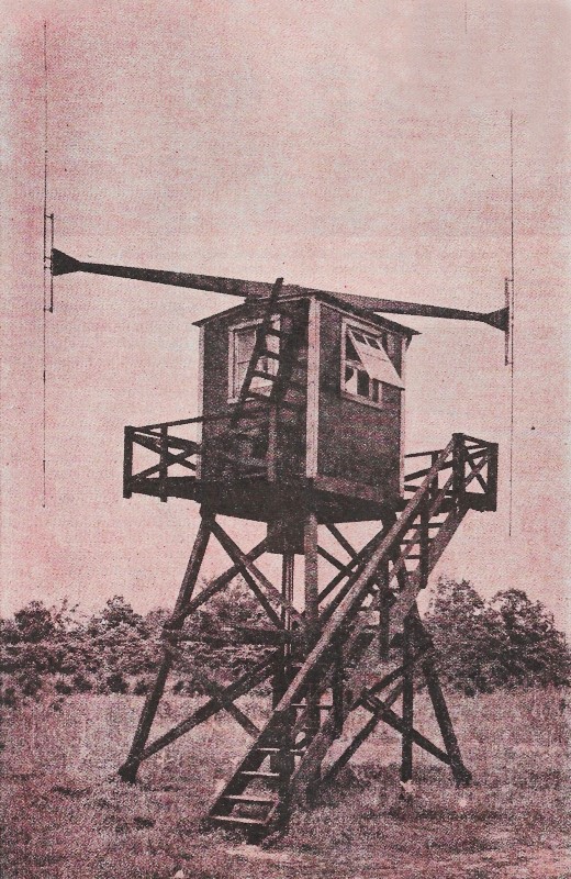
Adcock radio range ground station. Hundreds of these stations were deployed around the U.S. alone.
The Adcock antenna is an antenna array consisting of four equidistant vertical elements which can be used to transmit or receive directional radio waves.
The Adcock array was invented and patented by British engineer Frank Adcock in 1919 as British Patent No. 130,490, and has been used for a variety of applications, both civilian and military, ever since. Although originally conceived for receiving low frequency (LF) waves, it has also been used for transmitting, and has since been adapted for use at much higher frequencies, up to ultra high frequency (UHF).
In the early 1930s, the Adcock antenna (transmitting in the LF/MF bands) became a key feature of the newly created radio navigation system for aviation. The low frequency radio range (LFR) network, which consisted of hundreds of Adcock antenna arrays, defined the airways used by aircraft for instrument flying. The LFR remained as the main aerial navigation technology until it was replaced by the VOR system in the 1950s and 1960s.
The Adcock antenna array has been widely used commercially, and implemented in vertical antenna heights ranging from over 40 m (130 feet) in the LFR network, to as small as 13 cm (5 inches) in tactical direction finding applications (receiving in the UHF band).[5][6]
Diagram from Adcock's 1919 patent, depicting a four-element monopole antenna array; active antenna segments are marked in red.[1]
27-meter (90-foot) diagonal spacing Japanese Adcock direction finder installation for 2 MHz in Rabaul
Frank Adcock originally used the antenna as a receiving antenna, to find the azimuthal direction a radio signal was coming from in order to find the location of the radio transmitter; a process called radio direction finding.
Prior to Adcock's invention, engineers had been using loop antennas to achieve directional sensitivity. They discovered that due to atmospheric disturbances and reflections, the detected signals included significant components of electromagnetic interference and distortions: horizontally polarized radiation contaminating the signal of interest and reducing the accuracy of the measurement.
Adcock-who was serving as an Army officer in the British Expeditionary Force in wartime France at the time he filed his invention-solved this problem by replacing the loop antennas with symmetrically inter-connected pairs of vertical monopole or dipole antennas of equal length. This created the equivalent of square loops, but without their horizontal members, thus eliminating sensitivity to much of the horizontally polarized distortion. The same principles remain valid today, and the Adcock antenna array and its variants are still used for radio direction finding.
In the late 1920s, the Adcock antenna was adopted for aerial navigation, in what became known as the low frequency radio range (LFR), or the "Adcock radio range". Hundreds of transmitting stations, each consisting of four or five Adcock antenna towers, were constructed around the U.S. and elsewhere.
The result was a network of electronic airways, which allowed pilots to navigate at night and in poor visibility, under virtually all weather conditions. The LFR remained as the main aerial navigation system in the U.S. and other countries until the 1950s, when it was replaced by VHF-based VOR technology. By the 1980s all LFR stations were decommissioned.
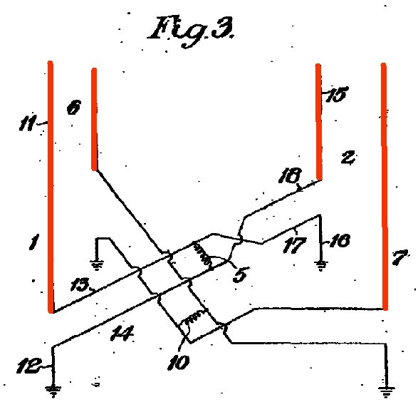
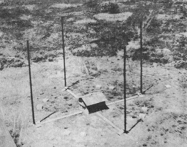
Diagram from Adcock's 1919 patent, depicting a four-element monopole antenna array; active antenna segments are marked in red.
27-meter (90-foot) diagonal spacing Japanese Adcock direction finder installation for 2 MHz in Rabaul.
ADCOCK RADIO DETECTION FINDING.
Source: Wikipedia.
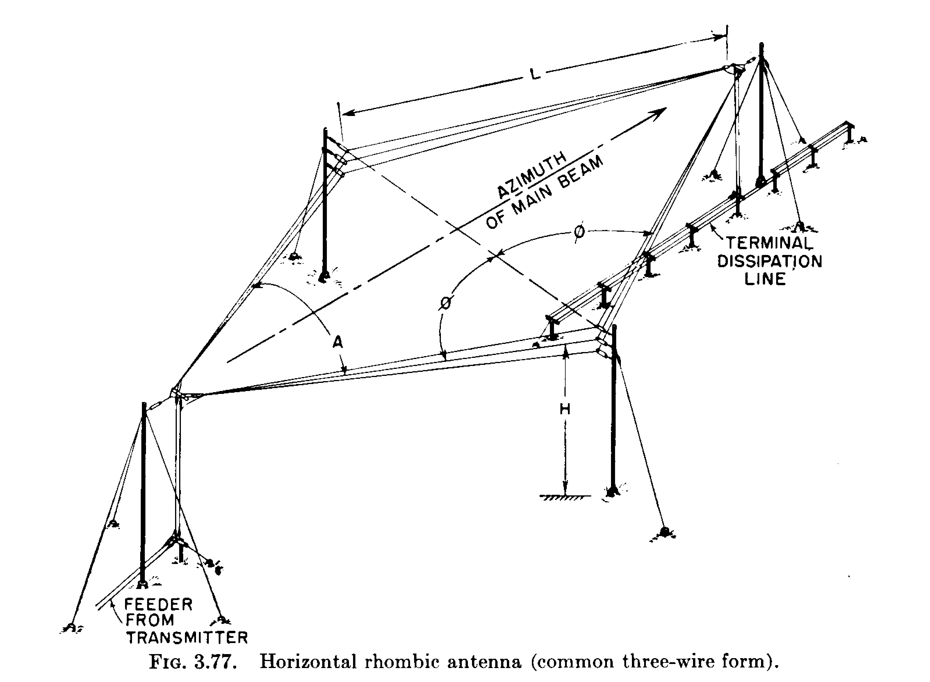
A rhombic antenna is made of four sections of wire suspended parallel to the ground in a diamond or "rhombus" shape. Each of the four sides is the same length - about a quarter-wavelength to one wavelength per section - converging but not touching at an angle of about 42° at the fed end and at the far end. The length is not critical, typically from one to two wavelengths (?), but there is an optimum angle for any given length and frequency. A horizontal rhombic antenna radiates horizontally polarized radio waves at a low elevation angle off the pointy ends of the antenna.
If the sections are joined by a resistor at either of the acute (pointy) ends, then the antenna will receive from and transmit to only the direction the end with the resistor points at. Its principal advantages over other types of antenna are its simplicity, high forward gain, wide bandwidth, and the ability to operate over a wide range of frequencies.
Diagram of radiation patterns of each segment of the antenna illustrates how it works. By using the correct vertex angle, one of the main lobes of each of the four sides point in the same direction, reinforcing each other, increasing the gain.
A rhombic antenna consists of one to several parallel wires suspended above the ground in a "rhombus" (diamond) shape. Long versions are typically supported by a pole or tower at each vertex to which the wires are attached by insulators. Each of the four sides is the same length. The length is not critical, typically from one to two wavelengths (?) end-to-end, but for any given length and frequency, there is an optimum acute angle at which the sections should meet.
A horizontal rhombic antenna radiates horizontally polarized radio waves at a low elevation angle off the acute end of the antenna opposite the feedline. Its principal advantages over other types of antenna are its simplicity, high forward gain and wide bandwidth, the ability to operate over a wide range of frequencies.
It is typically fed at one of the two acute (sharper angle) vertices through a balanced transmission line, or alternatively a coaxial cable with a balun transformer. The end of the wires meeting at the opposite vertex is either left open (unconnected), or is terminated with a non-inductive resistor. When resistor-terminated, the radiation pattern is unidirectional, with the main lobe off the terminated end, so this end of the antenna is oriented toward the intended receiving station or region. When unterminated, the rhombic is bidirectional with two opposite lobes off the two acute ends, but is not perfectly bi-directional.
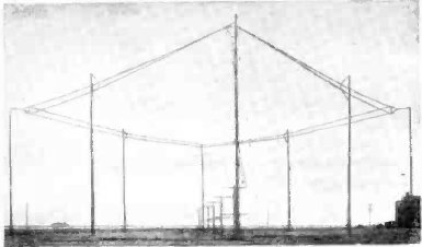
A horizontal three-wire rhombic antenna. This example is terminated with a resonant stub transmission line power reflector instead of a resistor to increase efficiency.
The rhombic antenna can radiate at elevation angles close to the horizon or at higher angles, depending on its height above ground relative to the operating frequency and its physical construction. Likewise, its beamwidth can be narrow or broad, depending primarily on its length. The shallow radiation angle makes it useful for skywave propagation, the longest distance mode for shortwave, in which radio waves directed into the sky at the horizon reflect from layers in the ionosphere and return to Earth far beyond the horizon.
It is possible to improve the low efficiency and gain of unidirectional rhombics by replacing the termination resistor by a low-loss balanced resonant stub transmission line. This reflects the power that would have been wasted in the termination resistor back into the antenna with the correct phase to reinforce the excitation from the transmitter. This circuit can increase the radiation efficiency of transmitting antennas to the 70-80% range, at the cost of increased complexity.
AT&T 2 wire rhombic in Dixon, California, in 1937, used for telephone service to Shanghai, China
The rhombic antenna was designed in the 1931 by Edmond Bruce and Harald Friis. It was mostly commonly used in the high frequency (HF) or shortwave band as a broadband directional antenna.
Prior to World War II, the rhombic was one of the most popular point-to-point high frequency antenna arrays. After World War II the rhombic largely fell out of favour for shortwave broadcast and point-to-point communications work, being replaced by log periodic antennas and curtain arrays. Larger log periodics provide wider frequency coverage with comparable gain to Rhombics. Distributed feed curtains or HRS curtain arrays provided a cleaner pattern, ability to steer the pattern in elevation and azimuth, much higher efficiency, and significantly higher gain in less space. However, rhombic antennas are used in cases where the combination of high forward gain (despite the losses described above) and large operating bandwidth cannot be achieved by other means, or where a directional antenna is needed, but construction and installation costs must be kept low.
In addition to its use as a simple and effective transmitting antenna (as described above), the rhombic can also be used as an HF receiving antenna with good gain and directivity. For example, BBC Monitoring's Crowsley Park receiving station has three rhombic antennas aligned for reception at azimuths of 37, 57 and 77 degrees.
If the sections are joined by a resistor at either of the acute (pointy) ends, then the antenna will receive from and transmit to only the direction the end with the resistor points at. Its principal advantages over other types of antenna are its simplicity, high forward gain, wide bandwidth, and the ability to operate over a wide range of frequencies.
Diagram of radiation patterns of each segment of the antenna illustrates how it works. By using the correct vertex angle, one of the main lobes of each of the four sides point in the same direction, reinforcing each other, increasing the gain.
A rhombic antenna consists of one to several parallel wires suspended above the ground in a "rhombus" (diamond) shape. Long versions are typically supported by a pole or tower at each vertex to which the wires are attached by insulators. Each of the four sides is the same length. The length is not critical, typically from one to two wavelengths (?) end-to-end, but for any given length and frequency, there is an optimum acute angle at which the sections should meet.
A horizontal rhombic antenna radiates horizontally polarized radio waves at a low elevation angle off the acute end of the antenna opposite the feedline. Its principal advantages over other types of antenna are its simplicity, high forward gain and wide bandwidth, the ability to operate over a wide range of frequencies.
It is typically fed at one of the two acute (sharper angle) vertices through a balanced transmission line, or alternatively a coaxial cable with a balun transformer. The end of the wires meeting at the opposite vertex is either left open (unconnected), or is terminated with a non-inductive resistor. When resistor-terminated, the radiation pattern is unidirectional, with the main lobe off the terminated end, so this end of the antenna is oriented toward the intended receiving station or region. When unterminated, the rhombic is bidirectional with two opposite lobes off the two acute ends, but is not perfectly bi-directional.
A horizontal three-wire rhombic antenna. This example is terminated with a resonant stub transmission line power reflector instead of a resistor to increase efficiency.
The rhombic antenna can radiate at elevation angles close to the horizon or at higher angles, depending on its height above ground relative to the operating frequency and its physical construction. Likewise, its beamwidth can be narrow or broad, depending primarily on its length. The shallow radiation angle makes it useful for skywave propagation, the longest distance mode for shortwave, in which radio waves directed into the sky at the horizon reflect from layers in the ionosphere and return to Earth far beyond the horizon.
It is possible to improve the low efficiency and gain of unidirectional rhombics by replacing the termination resistor by a low-loss balanced resonant stub transmission line. This reflects the power that would have been wasted in the termination resistor back into the antenna with the correct phase to reinforce the excitation from the transmitter. This circuit can increase the radiation efficiency of transmitting antennas to the 70-80% range, at the cost of increased complexity.
AT&T 2 wire rhombic in Dixon, California, in 1937, used for telephone service to Shanghai, China
The rhombic antenna was designed in the 1931 by Edmond Bruce and Harald Friis. It was mostly commonly used in the high frequency (HF) or shortwave band as a broadband directional antenna.
Prior to World War II, the rhombic was one of the most popular point-to-point high frequency antenna arrays. After World War II the rhombic largely fell out of favour for shortwave broadcast and point-to-point communications work, being replaced by log periodic antennas and curtain arrays. Larger log periodics provide wider frequency coverage with comparable gain to Rhombics. Distributed feed curtains or HRS curtain arrays provided a cleaner pattern, ability to steer the pattern in elevation and azimuth, much higher efficiency, and significantly higher gain in less space. However, rhombic antennas are used in cases where the combination of high forward gain (despite the losses described above) and large operating bandwidth cannot be achieved by other means, or where a directional antenna is needed, but construction and installation costs must be kept low.
In addition to its use as a simple and effective transmitting antenna (as described above), the rhombic can also be used as an HF receiving antenna with good gain and directivity. For example, BBC Monitoring's Crowsley Park receiving station has three rhombic antennas aligned for reception at azimuths of 37, 57 and 77 degrees.
RHOMBIC ANTENNAS.
Rotatable direction finder.